
產品介紹
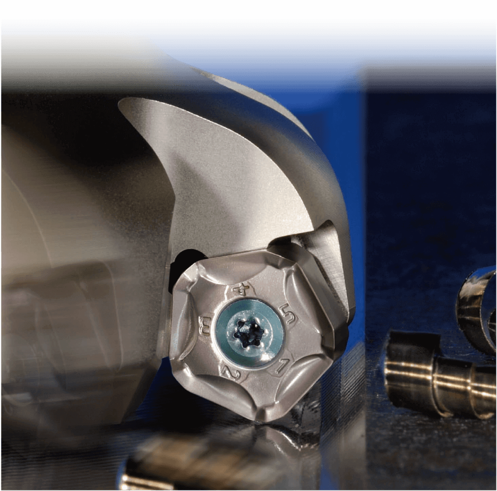
- Roughing and general-purpose facemill with 10-cornered pentagonal inserts


- Low cutting force due to helical cutting-edge design


- Fractures suppressed with double-edge position
Double-edge position
Major cutting edge makes chips thin, thereby reducing impact load at entrance and exit of workpiece

- Long tool life with PR12-Se Long tool life with PR12-Series MEGACOAT carbide inserts
MEGACOAT
Long tool life and high-speed milling due to high hardness and high oxidation resistance

- 3-dimensional chipbreaker improves chip evacuation
Smooth chip evacuation reduces chip-biting
·3-types of chipbreakers enable coverage of a wide range of milling conditions


